


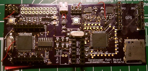
After having the boards for at least a month I finally built one up. This board dosn’t really do much new it is basically my GPS logging hardware v3.1 built onto one board. Since I was building my own boards I opted to use a atmega1284p since I was having issues running out of sram before (though I did clear that up in software). So there are two atmega1284p processors one to deal with the GPS and sensors, and another to talk to remote sensors as well as build and write the GPX file to the SD card. I also added an accelerometer and gyroscope to add to the data the sensor uC is collecting, I will probaly replace the atmega1284p on the sensor side with a atmega88 if the memory utilization is low enough, the 1284 seems a bit overkill for what it is doing.
As for the build there were a surprisingly few errors on this board as opposed to the atmega88 boards I worked on previously. For placing the paste and components I used a stencil rather then placing the paste with a toothpick as before. The stencil is nice but I did end up with alot more solder bridges then with the toothpick method, which worries me about the LGA components which I still haven’t tested.
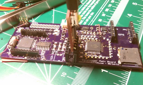
Once I got everything together I did know that I forgot a trace from the reset pin to the ISP connector on the left uC. Also found quicky that nothing was getting power since I forgot a trace to the enable pin of the voltage regulator. After all that I was still having issues reading anything other then 0x0,0x0,0x0 as a signature. Poking around for a bit longer showed that I had 10k ohm pull up resistors on the reset line, generally 1k is used. After swapping them out I was able to read the left uC without issue. The right uC was still giving problems, my first instinct is to pull the isolation resistors going from the uC to the gyroscope so I did. Pulling the resistors leaves pads on the SPI bus making it easy to probe. Probing showed normal operation on all lines for one transaction. What happened was I was missing a line from the ISP connector to the MISO line, so the programmer wasn’t getting anything back from the uC when it attempted to enter programming mode. So after these three mods I was able to successfully get Blink running on both processors.
The next step is to see what sensors and external components will work. I am fairly confident that the GPS and SD card should work, the aaccelerometer and gyro may be a bit more tricky.

[…] order to get some of the features like serial ports and I2C working on my atmega1284p chips, I needed to update the Sanguino core I have been using. The latest one published is based off […]