Random Projects and Comments

Home Archive for category "Hardware"

New Project – Scorpion/OpenCV

Scorpion Side
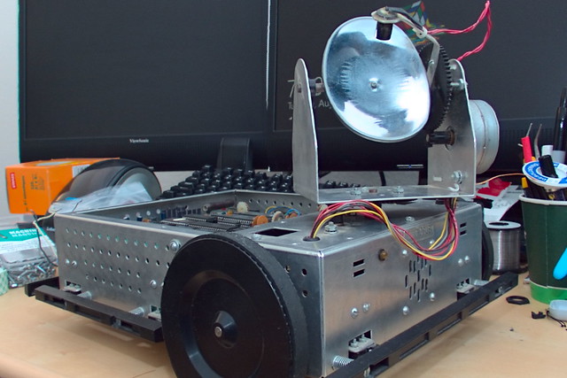
I’ve had this Scorpion robot platform for a long time.  It was given to me by my uncle in the early to mid 1990’s is my best guess.  The kit was made by Rhino Robots in 1984.  From what I can tell they are still around though do not produce the Scorpion anymore.

Scorpion Orginal Board
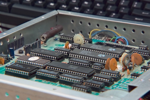
The Scorpion was built around a Motorola 6502 controller, with the motor control offloaded to dedicated stepper drivers.  Since it was designed from the beginning to be a research tool, the motors, bumpers, lights, and sensors are completely separate from the processor board.  For this reason its very easy to add whatever processor board you want.  In the past I’ve built boards from some of the early Atmel 8-bit processors ( the AT90S1200 comes to mind ).  Later on I had an arduino board.

ManualManual- DatasheetManual - Code

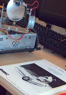
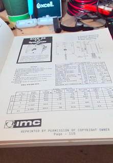
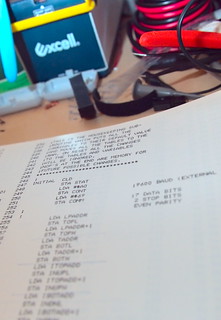
Since this was developed long before the internet was common place everything is in there.  Datasheets, code, lengthy descriptions on how every system interacts.  I don’t know of any manuals that even comes close to the detail in the Scorpion’s manual.

ScorpianEyes

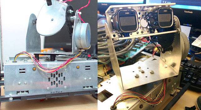
Recently I got introduced to the OpenCV project by a fellow member of Makers in Manchester and needed a platform to play with it on.  To that end I decided I should be able to adapt the Scorpion to work well with that.   I’ve already fitted some cameras to the spot where it originally had a single CdS cell for ‘image’ sensing.  The plan for processing is to run the cameras and vision and control through a Raspberry Pi and an atmega 1284p for the motor control.   Ultimately I would like to build a single board system though, more like the original robot used.  Would make a good project to learn how to design boards around the ARM chips I would likely need for the OpenCV system, and possibly intregrate the motor control onto that same chip.


GPS Logger Hardware v5.0

Published on March 20, 2012, by in Hardware.

DSCN0933
Got another rev of the Skiing Datalogger, I had REV:B boards made but never built one up since I knew of the issue with the gyro and the holes didn’t line up with the case. This board is REV:C which I added some holes, all the flying wires are gone (so far) except the rework of the Venus GPS module which Sparkfun has changed in their new version. I have tested the individual components. Only the accelerometer is giving me issues at the moment. It is doing the same thing as the 6dof board though so it could be something in my code.
Datalogger Front Panel v1
I also had a board to be used as a front panel made, mainly to give a better way to connect to the remote keypad but it also serves as a place to LEDs and switches. The LEDs are bottom entry mounted on the back of the panel. Switches being surface mount on the front. (more…)


New Datalogger User Interface

Published on February 4, 2012, by in Hardware.


Previously I have used this interface sewn into a glove to start new tracks in the GPX file and also give me a visual indication that the device is logging data.  The main problem with this system is I can not come up with a good way of disconnecting the glove from the wire to the base unit making taking the jacket and gloves on and off a challenge.   It happens that Sparkfun has a nice ‘wearable keypad’ that I decided to use.  The keypad has a 4-way directional switch, a center switch, and a LED which lights it up.  All the switches and LED reference a single ground pin which is the same method I used for the glove interface so this was a drop in replacement.

Rather then attaching the keypad to the glove again I opted to attach it to the jacket, which should take care of the issue around removing and putting on the jacket.  I also did not want to sew it onto the jacket just yet, so I just pushed some wire through the excess rubber around the keypad making some loops that the strap in the jacket can pass through.

Hoping to try this setup out tomorrow, and collect some more data.


GPS Logger Hardware v4.2

DSCN0923

I didn’t change anything with the electronic parts, but did get a new case for the data logger.  I tried long and hard but could not find a way to fit the GPS antenna inside the case.  The Molex connector goes to the  status LED and switch shown earlier.  The switch I changed from being a run/stop switch to just switching power, which allows me to get everything packaged up the night before. The usual status LEDs are inside the case, but are not visible during operation, which seems to be ok.
DSCN0929

The board doesn’t line up with any of the mounting holes, even REV:B which I added mounting holes do not line up, I am pretty sure I can modify the board to fit these mounting holes though.  Over all this case it larger then I would like, hopefully with some other modifications I can get the size down a bit.  Putting it into this case did stabilize the device quite a bit, I had a good run which I will talk about in another post where it did not reset all day and churned out some very nice data.


GPS Logger Hardware v4.1

DSC_0079
I’m now back to the same functionality I had on the version I built on proto boards though now much smaller. I added a run/stop switch on the side. Each transition from stop to run will result in a new file being started. Two lights on the top, the green one is lit when the uC is in a ‘RUN’ state, the red one flashes after each track point is written to the SD card.
DSC_0071
Since the plan is to use this while skiing I used a LilyPad wearable switch and LED sewn into a glove for status and control. The LED is just a duplication of the SD write led on the case. As long as it is blinking, there should be data being written to the card. Each push of the switch will result in a new track segment started ( and the old one closed ).  I couldn’t find any of my LED LilyPad stuff so I de-soldered one of the switches and mounted a 1206 LED across the pins. The glove is connected back to the main box with a three conductor ribbon.
Hopefully will be trying this setup out tomorrow, interested to see if it actually works.


GPS Logger Hardware v4.0

IMAG0620
After having the boards for at least a month I finally built one up.  This board dosn’t really do much new it is basically my GPS logging hardware v3.1 built onto one board.  Since I was building my own boards I opted to use a atmega1284p since I was having issues running out of sram before (though I did clear that up in software).  So there are two atmega1284p processors one to deal with the GPS and sensors, and another to talk to remote sensors as well as build and write the GPX file to the SD card. I also added an accelerometer and gyroscope to add to the data the sensor uC is collecting, I will probaly replace the atmega1284p on the sensor side with a atmega88 if the memory utilization is low enough, the 1284 seems a bit overkill for what it is doing.
(more…)


Yikes! Invalid device signature.

Published on September 4, 2011, by in Hardware.

So, I got my PCBs in yesterday, imediatly grabbed the solder paste put a bunch of components down, reflowed them and everything looked good.  The power supply was actully very stable, even the components that didn’t have leads looked to be good.  I did know of some errors on the board such as not running VCC, GND, and RST to the ISP header.  Tying AREF to VCC rather then decoupling it. Fixed thoes issues, in the case of AREF I just cut the trace and moved on, no decoupling added. Oh an the biggest oversight on the board design was I left off the power connector.

Many attempts at fixing a non-existent hardware problem.

Many attempts at fixing a non-existent hardware problem.

Imediatly after getting everything fixed, and hooking it up to my ISP programmer I started getting the message that was going to haunt me for the next 24hrs or so.

avrdude: Device signature = 0x000000
avrdude: Yikes! Invalid device signature.

I tried everything, followed every trace, added decoupling caps everywhere!  Finally I decided I must have fried the chip when reflowing it and built up another board.  Same results (this one the power supply wasn’t nearly as clean though, need to fix that).

MOSI - Blue, MISO - Yellow , The slave would answer but would fail to read the signature correctly.

What was really bugging me is that I was seeing traffic on both MOSI and MISO which ment both devices were talking to eachother at some point.  I decided it must be something with the board design, went back to the computer and checked everything.  Ran across a couple of posts that mentioned SPI clock speed being an issue, as these are new devices they are set to run off the internal oscillator which is 8mhz, with the divide by 8 fuse set resulting in a 1mhz clock.  Come to find out the default SPI rate in avrdude is  roughly 1mhz which will work for devices running at 4mhz or higher.  Setting the SPI clock down caused avrdude to imediatly recognize the chip as valid on both boards I built.  Tomorrow will be filled with trying to get a bootloader on them, and seeing what if any data I can get in and out of the sensors on the chip.


Homemade Flex Circuit Boards

Published on July 24, 2011, by in Hardware.

DSCN0853

A while ago I came up with an idea for a project that seemed to require a flexible LED matrix. I could not find any comerically available, and even flexible LCDs aren’t nearly as common as I would expect. Getting a custom flexiable PCB created is possible, but pretty expensive and not exactly easy. Seeing as a LED matrix is a pretty simple circuit I started looking around for a way to make something at home.

(more…)

 
credit
© Ryan M Sutton, 2015