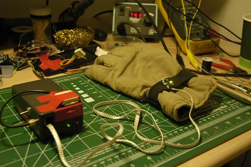
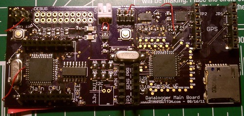
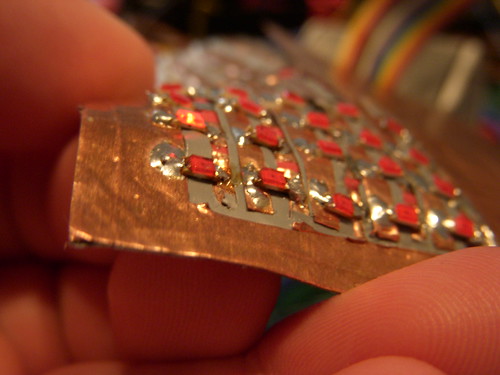
So, I got my PCBs in yesterday, imediatly grabbed the solder paste put a bunch of components down, reflowed them and everything looked good. The power supply was actully very stable, even the components that didn’t have leads looked to be good. I did know of some errors on the board such as not running VCC, GND, and RST to the ISP header. Tying AREF to VCC rather then decoupling it. Fixed thoes issues, in the case of AREF I just cut the trace and moved on, no decoupling added. Oh an the biggest oversight on the board design was I left off the power connector.

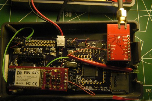
Many attempts at fixing a non-existent hardware problem.
Imediatly after getting everything fixed, and hooking it up to my ISP programmer I started getting the message that was going to haunt me for the next 24hrs or so.
avrdude: Device signature = 0x000000

avrdude: Yikes! Invalid device signature.
I tried everything, followed every trace, added decoupling caps everywhere! Finally I decided I must have fried the chip when reflowing it and built up another board. Same results (this one the power supply wasn’t nearly as clean though, need to fix that).

MOSI - Blue, MISO - Yellow , The slave would answer but would fail to read the signature correctly.
What was really bugging me is that I was seeing traffic on both MOSI and MISO which ment both devices were talking to eachother at some point. I decided it must be something with the board design, went back to the computer and checked everything. Ran across a couple of posts that mentioned SPI clock speed being an issue, as these are new devices they are set to run off the internal oscillator which is 8mhz, with the divide by 8 fuse set resulting in a 1mhz clock. Come to find out the default SPI rate in avrdude is roughly 1mhz which will work for devices running at 4mhz or higher. Setting the SPI clock down caused avrdude to imediatly recognize the chip as valid on both boards I built. Tomorrow will be filled with trying to get a bootloader on them, and seeing what if any data I can get in and out of the sensors on the chip.