


Bit of a delay moving on this project, mainly because an error in the board I was building to mount the SUP500f GPS to had an error which fried it. Since sparkfun stopped selling SUP500f I had to find another GPS module. I ended up not going with the recommended replacement mainly due to the odd SMT connector in the middle of the device, I have no reason to this but it just felt like that would not work very well.
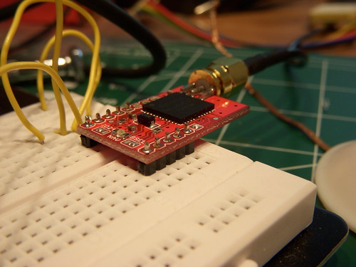
Instead I went with the Venus634FLPx which sparkfun provides on a nice breakout with an SMA connector for the antenna. The external antenna also gave some more flexibility on the mounting which I will get to later. The nice thing about all these modules ( and most on the market ) is that they just spit out standard NEMA sentences so no code modification was needed between the SUP500F and the Venus modules.
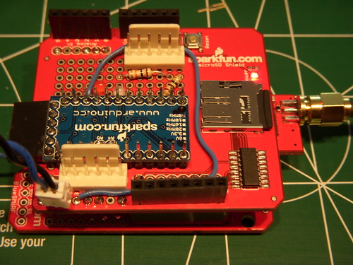
While along with the GPS I picked up another Arduino Mini 3.3v to run the GPS rather then the lilypad, and a protoshield for tying it all together. I reworked the main processor board by removing the regular headers and adding the stackable headers from the protoshield, and put regular headers onto the protoshield. This allows the stacking of the board and some lines of communication ( Though I only need 4 at this time ) So if your keeping track, yes I am using two arduino shields in the project, and neither of them is being used as designed.
In a similar manner as the main board I mounted the Arduino Mini onto the protoshield, as well as the Venus GPS module. The wireing on this one is much simpler, and the GND and VCC rails on the protoshield all make this one much neater.
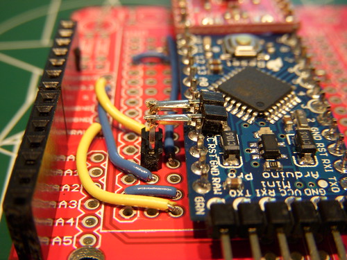
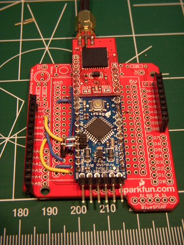
Unfortunately A4 and A5 on the Arduino Mini are put in about the worst possible positions, I’m still trying to find a good way to bring these out to a board. My attempt this time I mounted a right angle header on the top of the Arduino this brings the pins out right between the neighboring pins. Another right angle header is mounted to the board to bring the signals down.
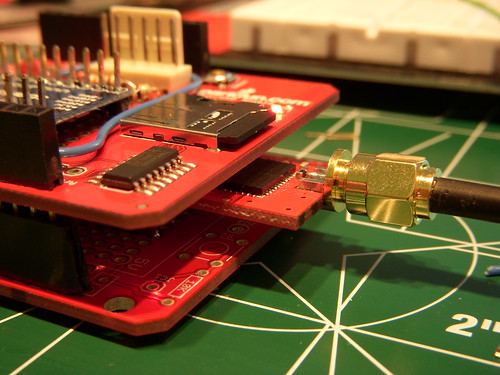
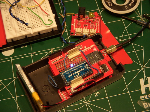
Once the pieces are put together the whole package is fairly compact, and _almost_ fits into the enclosure I intended. Actually everything fits but the battery which may be able to be made smaller.
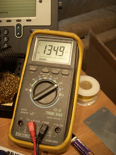
Speaking of batteries, I did some basic power consumption measurements. The highest current draw occurs during acquisition which is about 135ma. Once the GPS has a fix the draw begins pulsing which makes sense. According to the averaging function on my multimeter the 5min average is 94ma.
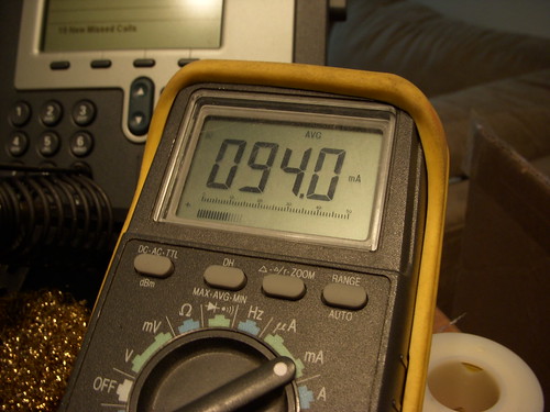
Since this is defiantly not going to be a consent current system due to the voltage regulators in the Arduinos I need to do some more measurements to make a guess at battery capacity, but ~100ma running current is much better then I was initially expecting
I am hoping to log some actual tracks again tomorrow now that everything fits neatly into a box now.

Hey cool project. Is there any chance you can tell me which pins are connected between the arduino and the GPS?
[…] a month I finally built one up. This board dosn’t really do much new it is basically my GPS logging hardware v3.1 built onto one board. Since I was building my own boards I opted to use a atmega1284p since I […]